 Skip to content
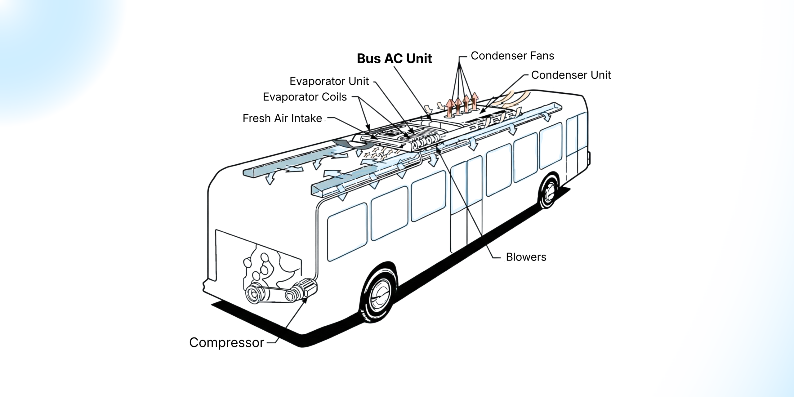
Introduction
Every day, millions of passengers across India and the wider world board buses – intercity coaches, school buses, city transit vehicles, and luxury touring coaches – expecting a thermally comfortable environment inside the cabin. For many of these journeys, particularly in tropical and arid climates where ambient temperatures routinely exceed 40°C, that comfort is delivered by a sophisticated engineering system working silently overhead or at the rear of the vehicle: the bus air conditioner.
Yet despite the ubiquity of bus air conditioning, the technology that powers it remains poorly understood outside engineering circles. How does a system mounted on a rooftop maintain cabin temperatures of 24–26°C when the air outside is at 45°C? How does it manage the body heat of 50 occupants, the solar radiation streaming through large windows, and the radiant heat rising from an asphalt road – all simultaneously, and for hours at a stretch?
This article provides a thorough, accessible explanation of how bus air conditioning systems work. It covers the underlying thermodynamic principles, the function of each key component, the different system architectures used across the industry, the unique challenges of tropical and high-ambient climates, and the distinct engineering requirements of electric bus applications.
Whether you are a fleet operator, a transport engineer, an OEM procurement professional, or simply a curious reader, this guide is intended to build a confident, working understanding of one of transport technology’s most consequential passenger-comfort systems.
Key Takeaway: A bus air conditioning system is not simply a scaled-up version of a passenger car’s AC unit. It is a purpose-engineered, high-capacity thermal management system designed to handle large occupancy loads, intense solar heat gain, sustained high ambient temperatures, continuous-duty operation, and – increasingly – integration with electric drivetrains, all within the structural and weight constraints of a commercial vehicle.
1. The Science: The Vapour-Compression Refrigeration Cycle
All conventional bus air conditioning systems – regardless of manufacturer, configuration, or application – operate on the same fundamental thermodynamic principle: the vapour-compression refrigeration cycle. Understanding this cycle is the essential first step in understanding how bus AC works.
What Is Refrigeration?
Refrigeration, in engineering terms, is the process of transferring thermal energy (heat) from a lower-temperature region to a higher-temperature region. This runs counter to the natural direction of heat flow – which is always from hot to cold – and therefore requires the input of external mechanical energy to drive it.
The working fluid that facilitates this heat transfer is called a refrigerant. The refrigerant’s defining property is its ability to change phase – from liquid to vapour and back again – at temperatures and pressures that are practical within a vehicle’s operating environment. It is this phase-change behaviour that makes large-scale heat transfer possible within a compact system.
The Four Stages of the Refrigeration Cycle
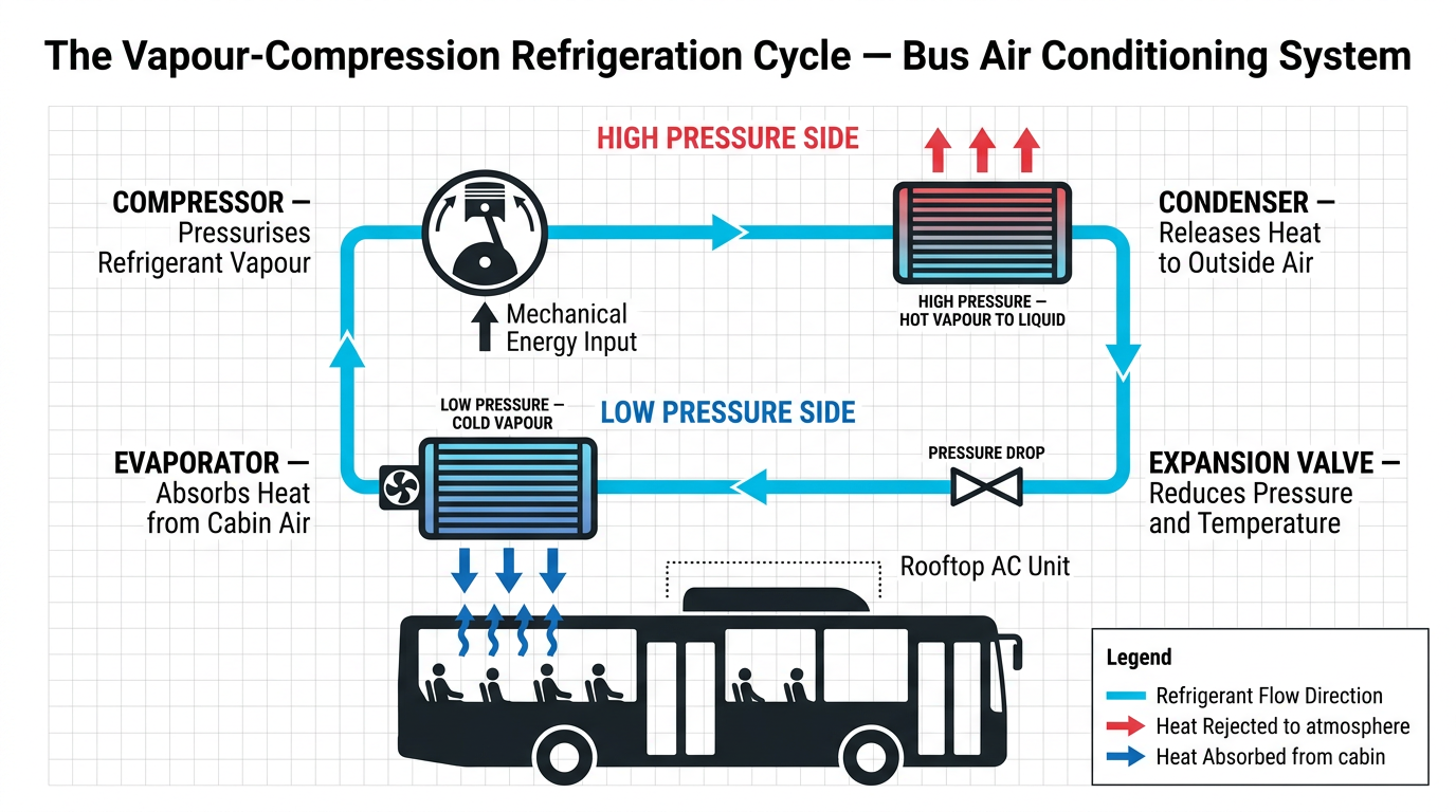
Stage 1 – Compression
The refrigerant begins its cycle as a low-pressure, low-temperature vapour. The compressor draws in this vapour and compresses it mechanically, raising both its pressure and temperature significantly. The refrigerant exits as a high-pressure, high-temperature superheated vapour. This is the stage that requires the input of mechanical energy – the driving force behind the entire system.
In a conventional diesel or CNG bus, this energy is typically drawn from the vehicle engine via a belt-driven pulley and an electromagnetic clutch. In an electric bus, an electric motor drives the compressor directly from the high-voltage battery system.
Stage 2 – Condensation
The hot, high-pressure refrigerant vapour travels to the condenser, typically mounted on the exterior of the rooftop unit where it is exposed to the airstream. Here, the refrigerant releases its heat to the external atmosphere and transitions from a superheated vapour to a high-pressure liquid. This is the stage at which the heat extracted from inside the bus is ultimately rejected to the air outside.
Condenser efficiency is critically important in hot climates. When ambient temperatures approach 45–48°C – conditions commonplace across the North Indian plains, Rajasthan, and parts of the Arabian Peninsula during peak summer – the temperature differential between the refrigerant and the external air is reduced, making heat rejection harder and placing greater demand on the compressor.
Stage 3 – Expansion
The high-pressure liquid refrigerant passes through an expansion device – most commonly a Thermostatic Expansion Valve (TXV) or, in more advanced systems, an Electronic Expansion Valve (EXV). This device causes a sudden, controlled drop in pressure, which simultaneously produces a sharp fall in the refrigerant’s temperature. The refrigerant emerges as a cold, low-pressure liquid-vapour mixture, now ready to absorb heat.
The precision with which the expansion device meters refrigerant flow is central to system efficiency. Electronic expansion valves, governed by the vehicle’s HVAC control unit, offer superior modulation capability across varying load conditions compared with purely mechanical alternatives.
Stage 4 – Evaporation
The cold refrigerant enters the evaporator, positioned inside or directly supplying the passenger cabin – typically within the rooftop unit or in distributed ceiling cassettes. A blower fan draws warm cabin air across the evaporator’s finned surface. The refrigerant absorbs heat from this air and evaporates, turning back into a low-pressure vapour. The cooled air is then recirculated into the cabin, progressively lowering the passenger-space temperature.
The low-pressure vapour is drawn back into the compressor, and the cycle recommences – continuously, for the entire duration of the vehicle’s operation.
Coefficient of Performance
System performance is measured by the Coefficient of Performance (COP) – the ratio of heat removed from the cabin to the mechanical work input by the compressor. A higher COP indicates greater energy efficiency. In well-designed bus air conditioning systems, COPs typically range from 2.0 to 3.5 depending on ambient conditions and system load. A COP of 2.5, for example, means the system removes 2.5 units of heat from the cabin for every 1 unit of electrical or mechanical energy consumed.
2. Key Components of a Bus Air Conditioning System
While the refrigeration cycle provides the thermodynamic framework, it is the physical components through which this cycle operates that determine system performance, reliability, and service life. Each component in a bus AC system is engineered to withstand the specific stresses of commercial transport operation: continuous vibration, road dust ingestion, high ambient temperatures, and duty cycles that may extend to 14–16 hours per day.
The Compressor
The compressor is the mechanical heart of the refrigeration system. In bus applications, compressors are typically of the swash-plate piston or scroll design, selected for their compact form factor, high volumetric efficiency, and tolerance of vibration.
Fixed-displacement compressors maintain a constant swept volume per revolution, with cooling capacity modulated by engaging or disengaging an electromagnetic clutch. Variable-displacement compressors adjust their swept volume continuously in response to system demand, delivering markedly superior part-load efficiency – a meaningful advantage on routes with variable passenger loading or fluctuating ambient conditions.
In engine-driven configurations, the compressor imposes a parasitic load on the bus engine of typically 5–15 kW depending on displacement and operating pressure, with direct implications for fuel consumption and exhaust emissions under BS VI norms.
The Condenser
The condenser in a bus application must dissipate the combined heat of the refrigeration load (heat removed from the cabin) and the equivalent of the compressor work input. In a fully loaded bus operating in 45°C ambient conditions, total heat rejection can exceed 30–35 kW.
Condensers are typically constructed using brazed aluminium microchannel or copper-fin aluminium-tube technology. Microchannel designs offer superior heat-transfer efficiency per unit area, reduced refrigerant charge, and lower weight – attributes of particular value in modern vehicle design where roof-loading constraints are stringent.
Condenser fans – axial-flow or centrifugal designs – are sized to maintain adequate airflow even when the vehicle is stationary. In high-ambient conditions, insufficient condenser airflow results in elevated condensing pressure, compressor thermal overload, and ultimately system shutdown through high-pressure protection.
The Expansion Device
The expansion device meters the refrigerant flow from the high-pressure side to the low-pressure evaporator. Thermostatic Expansion Valves (TXV) use a temperature-sensing bulb at the evaporator outlet to regulate flow mechanically. Electronic Expansion Valves (EXV), governed by the HVAC control unit, provide faster response, finer modulation, and the ability to integrate with intelligent energy management strategies – making them the preferred choice in modern and electric bus applications.
The Evaporator
The evaporator is the interface between the refrigeration circuit and the passenger cabin. Warm cabin air passes across the evaporator’s finned surface, transferring its heat to the refrigerant within. The cooled, dehumidified air is then distributed into the passenger space.
A critical secondary function of the evaporator is dehumidification. As warm, humid cabin air contacts the sub-zero evaporator surface, moisture condenses on the fins and is drained away through a condensate drainage system. This is especially important in monsoonal and coastal climates where relative humidity can exceed 80–90%, and where uncontrolled cabin humidity can cause passenger discomfort and interior condensation damage over time.
The Control System
Modern bus air conditioning systems are governed by a dedicated HVAC Electronic Control Unit (ECU), which monitors a network of sensors – cabin temperature, evaporator outlet temperature, refrigerant pressures, cabin humidity, and solar radiation – to maintain the desired setpoint with minimum energy consumption.
Advanced control features include PID-based temperature regulation, predictive load algorithms, CAN bus integration with the vehicle’s central ECU, and remote diagnostics via telematics interfaces. The latter allows fleet operators to monitor system health, detect fault codes, and schedule maintenance interventions before in-service failures occur.
Air Distribution and Ducting
The ducting and air distribution system determines whether the conditioned air produced at the evaporator actually reaches passengers uniformly throughout the cabin. A well-designed distribution system delivers supply air at 0.5–1.5 m/s at the passenger-zone level – sufficient for effective heat removal without creating uncomfortable draughts – and maintains temperature uniformity within ±2°C across the cabin length.
The ratio of fresh outside air to recirculated cabin air – the OA/RA ratio – is a further key design parameter, balancing indoor air quality requirements against the energy cost of conditioning warm external air.
3. Types of Bus Air Conditioning Systems
Bus air conditioning systems are classified by their configuration, power source, and physical mounting arrangement. Selection of system type depends on vehicle length and type, route profile, operational requirements, and drivetrain technology.
Rooftop Integrated Units
The most prevalent configuration for intercity coaches, school buses, and luxury touring coaches is the rooftop integrated unit, in which the compressor, condenser, expansion device, evaporator, and control electronics are housed within a single self-contained assembly mounted on the vehicle roof.
The compressor is belt-driven from the engine’s auxiliary drive. Refrigerant lines and electrical connections pass through the roof into the unit above. Conditioned air is delivered via longitudinal ceiling ducts running the length of the passenger compartment.
Rooftop units keep the refrigerant circuit outside the passenger cabin, simplifying maintenance access and limiting passenger exposure to refrigerant in the event of a circuit leak. The principal engineering consideration is aerodynamic drag and the concentration of weight at roof height, which must be accounted for in the vehicle’s centre-of-gravity and rollover safety calculations.
Split Systems
In split configurations, the condensing unit (compressor and condenser) is mounted separately – at the rear of the vehicle, within an engine-compartment panel, or in a dedicated mechanical bay – while evaporator cassettes are distributed along the cabin ceiling.
Split systems offer greater flexibility for articulated buses, double-deckers, and other long-wheelbase configurations where a single rooftop unit cannot provide sufficient or adequately uniform cooling across the full cabin length.
Independent Auxiliary Units
In applications such as overnight intercity coaches, the air conditioning system may be powered by a dedicated auxiliary power unit (APU) rather than the main traction engine. This allows the cabin to be conditioned while the engine is switched off – for example, during driver rest stops – without the fuel consumption, emissions, and noise associated with main engine idling.
The APU may be a compact diesel generator or, increasingly, an electric auxiliary unit drawing from a dedicated battery bank, the latter being particularly relevant in the context of low-emission zone regulations and fleet electrification programmes.
Electric Bus HVAC Systems
Electric buses represent a rapidly growing segment of new bus procurement globally, driven by zero-emission mandates, government support schemes such as India’s FAME II programme, and the total cost of ownership (TCO) advantages of electric drivetrains over extended operational horizons.
In an electric bus, the absence of an engine-driven compressor fundamentally alters the HVAC system architecture. The refrigeration compressor is driven by a dedicated electric motor – fixed-speed or variable-frequency-drive (VFD) – powered directly from the high-voltage (HV) battery pack, which typically operates at 400–750 V DC in contemporary electric bus platforms.
This introduces two principal engineering challenges:
Range impact: HVAC power consumption can account for 20–40% of total energy consumption in an electric bus under peak summer conditions, significantly reducing driving range per charge. This necessitates careful energy management strategies, including cabin pre-conditioning while the bus is connected to a depot charger (thereby using grid energy rather than battery energy for the initial cool-down), variable-speed compressor operation, and intelligent load-shedding protocols coordinated with the battery management system (BMS).
Battery and powertrain thermal management integration: Electric buses require not only cabin cooling but also Battery Thermal Management Systems (BTMS) – to keep the battery pack within its optimal operating temperature window of typically 15–35°C – and
Traction Cooling Systems (TCS) for the motor, inverter, and associated power electronics. These three thermal sub-systems must operate in coordination, sharing information about thermal state, energy availability, and priority to maintain overall vehicle efficiency and battery longevity. This integration is one of the more complex engineering challenges in electric bus design.
4. The Thermal Load: Understanding What Bus AC Must Overcome
To appreciate the engineering demands placed on a bus air conditioning system, it is necessary to understand the magnitude and diversity of the thermal loads it must overcome.
Occupancy Heat Gain
Each seated passenger generates approximately 100–120 W of metabolic heat under normal conditions (ASHRAE Fundamentals, Chapter 9). A fully occupied 50-seat bus therefore presents an occupancy heat load of 5,000–6,000 W from passengers alone – before any external heat sources are considered.
Solar Heat Gain
A bus’s large glazed areas – side windows, front windscreen, and sometimes roof glazing – admit substantial solar radiation. Solar heat gain through a standard 4 mm clear glass window can reach 500–700 W/m² under direct summer sunlight, depending on orientation and latitude. For a bus with 12–15 m² of glass area, this translates to a solar load of 6,000–10,500 W or more – comparable to, or exceeding, the occupancy load alone.
Solar-reflective and low-emissivity (low-e) glazing can reduce solar heat gain by 40–60%, significantly reducing the peak cooling load and thereby lowering the required AC system capacity and associated energy consumption.
Conduction Through the Body Structure
Heat is also conducted into the cabin through the bus body panels, floor, and roof from the hot external environment. This conductive load depends on the vehicle’s insulation specification – the thermal resistance (R-value) of roof panels, side walls, and floor construction – and is a factor that bus body builders and HVAC system designers must assess jointly during the vehicle design phase.
In a well-insulated modern coach with 50 mm polyurethane foam insulation in the side walls and roof, conductive heat gain at 45°C ambient may be in the range of 2,000–4,000 W. In a poorly insulated vehicle of the same external dimensions, this figure can be considerably higher.
Ventilation and Fresh Air Load
The requirement to introduce fresh outside air – mandated by occupancy and CO₂ concentration limits – brings a further thermal load, as the hot, humid external air must be cooled and dehumidified before supply to the cabin. This is known as the ventilation load or outdoor air load and can be a significant proportion of total system capacity in climates where the outside air enthalpy is high..
Total Design Cooling Load
The sum of the above components – occupancy heat, solar heat, conduction, ventilation, and ancillary internal heat sources (lighting, electronic displays, driver equipment) – constitutes the total design cooling load of the bus. Accurately calculating this load, across all anticipated operating conditions, is the starting point for correct AC system selection.
Oversizing the system increases weight, cost, and energy consumption; undersizing results in inadequate cooling performance under peak conditions.
5. Climate-Specific Engineering: The Tropical Challenge
The bus air conditioning design envelope for tropical and high-ambient climates – which includes much of the Indian subcontinent, Southeast Asia, the Middle East, and sub-Saharan Africa – is substantially more demanding than that applicable in temperate regions.
High Ambient Temperatures: Design outdoor temperatures of 45–50°C in parts of North India, Rajasthan, and the Arabian Peninsula require systems sized for extreme condensing pressures and correspondingly higher compressor discharge temperatures. Components must be selected and qualified for operation at these conditions, not merely at the 35°C ambient temperature assumed in many European or North American standards.
High Humidity: Coastal and monsoonal regions combine high temperatures with relative humidity levels of 70–95%. High ambient humidity significantly increases the ventilation load, as the moisture content of the incoming air must be reduced through condensation at the evaporator before it can be supplied to the cabin. This places additional demand on evaporator surface area, drain capacity, and refrigeration capacity.
Road Vibration and Dust: Indian road conditions, particularly on state and rural highways, subject vehicle components to sustained vibration, shock loads, and airborne dust ingestion. Bus AC components – particularly the compressor, expansion valves, and electrical connections – must be engineered and tested to appropriate vibration and ingress-protection standards (IP ratings per IEC 60529) for reliable long-term service in these conditions.
High Altitude Routes: Buses operating on Himalayan or Deccan Plateau routes at elevations of 1,500–3,500 m experience significantly reduced air density. Reduced air density diminishes condenser fan airflow effectiveness and can affect compressor volumetric efficiency. Systems intended for mixed-altitude operations must be designed to maintain adequate performance across the full operating altitude range.
6. Refrigerants and Environmental Responsibility
The refrigerant used in a bus air conditioning system has environmental implications that extend well beyond the vehicle itself. Fluorinated greenhouse gases (F-gases), including the historically dominant R-134a, carry Global Warming Potentials (GWPs) many hundreds to thousands of times greater than carbon dioxide – meaning that even small refrigerant leaks have a disproportionate climate impact.
The Kigali Amendment to the Montreal Protocol, adopted in 2016 and ratified by India in August 2021, establishes a binding international schedule for the phase-down of HFC refrigerants. India’s agreed pathway requires an 80% reduction in HFC consumption relative to the 2024–2026 baseline, to be achieved by 2047, with the first freeze in consumption levels expected around 2028.
For the bus and commercial vehicle industry, this regulatory trajectory has direct implications for refrigerant selection in new system design and for the servicing of existing fleets. Transition refrigerants with lower GWP – including HFO-based blends and, in longer-term applications, natural refrigerants such as CO₂ (R-744) – are progressively entering commercial service.
Responsible refrigerant management – including leak-tight system design, refrigerant recovery during servicing, and accurate charge recording – is not merely good engineering practice; it is an increasingly explicit legal obligation under national and international environmental regulation.
7. Maintenance and Operational Reliability
A bus air conditioning system operates under conditions of sustained mechanical stress, thermal cycling, and environmental exposure. Regular, structured maintenance is essential to sustaining cooling performance and preventing in-service failures that can strand passengers and incur costly unscheduled downtime.
Main maintenance activities include:
- Refrigerant charge verification: Correct system charge is fundamental to performance. Refrigerant leaks should be detected early using electronic leak detectors and repaired promptly.
- Condenser and evaporator cleaning: Dust and debris accumulation on fin surfaces impairs heat transfer and reduces system efficiency. Condenser coils exposed to road dust require periodic cleaning, the frequency of which depends on route conditions.
- Compressor belt inspection and tensioning: Belt-driven compressors require periodic belt tension checks and belt replacement at manufacturer-specified intervals to prevent slippage and premature failure.
- Drain line inspection: Blocked evaporator drain lines cause condensate to accumulate within the cabin unit, leading to interior water ingress and the risk of mould growth.
- Filter replacement: Cabin air filters require replacement at regular intervals to maintain adequate airflow and indoor air quality.
- Control system diagnostics: HVAC ECU fault codes should be interrogated at each scheduled service interval. Remote telematics monitoring, where available, enables continuous health monitoring between physical inspections.
- Refrigerant recovery and handling: All refrigerant service work must be carried out by qualified technicians using certified recovery equipment, in accordance with applicable environmental regulations governing F-gas handling.
Structured preventive maintenance, carried out at manufacturer-recommended intervals, consistently delivers a measurable reduction in in-service failure rates and extends the operational life of key system components.
8. Trans ACNR and JTAC: Engineering Perspective
Trans ACNR Solutions Private Limited, established in 2003, is engaged in the design, development, and manufacture of thermal management systems for the transport industry. The company’s manufacturing and research facilities, spanning over 525,000 square feet across Ghiloth (Rajasthan), Malur (Karnataka), and Ras Al Khaimah (UAE), are dedicated to the engineering of bus air conditioning, railway HVAC, truck refrigeration, electric vehicle battery thermal management, and defence HVAC systems.
Trans ACNR’s bus air conditioning brand, JTAC, is engaged with original equipment manufacturers (OEMs), bus body builders, fleet operators, and transporters across the country, supplying systems for both internal combustion engine (ICE) and electric bus platforms.
The company holds ISO 9001:2015 (Quality Management), IATF 16949:2016 (Automotive Quality Management), ISO 14001:2015 (Environmental Management), and OHSAS 18001:2007 (Occupational Health and Safety) certifications, and operates a DSIR-Recognised In-House R&D Centre – a formal government acknowledgement of its research and development capabilities.
For further information on Trans ACNR’s product range, technical capabilities, or service network, visit www.transacnr.com.
Frequently Asked Questions
Q: How does a bus air conditioner work?
A bus air conditioner operates on the vapour-compression refrigeration cycle. A refrigerant circulates continuously through four key components – the compressor, condenser, expansion device, and evaporator – alternately absorbing heat from the passenger cabin and rejecting it to the external atmosphere. The net result is a sustained reduction in cabin temperature, regardless of external ambient conditions.
Q: What are the main components of a bus AC system?
The principal components are the compressor, condenser, thermostatic or electronic expansion valve, and evaporator. Ancillary components include blower fans, cabin air filters, refrigerant lines, a HVAC Electronic Control Unit (ECU), and the cabin air distribution ducting system.
Q: What refrigerants are used in bus air conditioners?
The most widely used refrigerant in current bus AC systems is R-134a (GWP = 1,430). The industry is progressively transitioning to lower Global Warming Potential alternatives – including R-1234yf (GWP < 1) and R-744/CO₂ (GWP = 1) – in response to the HFC phase-down schedule under the Kigali Amendment to the Montreal Protocol, ratified by India in 2021.
Q: How is electric bus AC different from conventional bus AC?
In an electric bus, the compressor is driven by an electric motor powered from the high-voltage battery pack, replacing the engine-driven belt arrangement of conventional buses. This requires coordinated energy management between the HVAC system, the battery management system (BMS), and the traction system. Electric buses also require Battery Thermal Management Systems (BTMS) and Traction Cooling Systems (TCS) that work in conjunction with the cabin HVAC.
Q: Why is bus AC more complex than car AC?
A bus carries 50–60 occupants, each generating approximately 100–120 W of body heat. Combined with large glazed surface areas admitting solar radiation, high ambient temperatures, and continuous-duty operation over long routes, the total cooling load of a bus is many times greater than that of a passenger car. Bus AC systems are correspondingly engineered to substantially higher capacity, reliability, and durability standards.
Conclusion
Bus air conditioning is far more than a passenger convenience. In tropical climates, it is a determinant of passenger health, driver alertness, and the commercial viability of bus-based public transport. The technology that delivers this comfort – the vapour-compression refrigeration cycle, executed through precisely engineered components and governed by intelligent control systems – represents decades of applied engineering development adapted specifically for the demands of commercial transport operation.
As the bus industry navigates the twin transitions of electrification and refrigerant phase-down, the engineering complexity of bus thermal management will only increase. Systems that once operated as standalone refrigeration units must now function as integrated sub-systems within a broader vehicle energy management architecture – responsive to battery state-of-charge, route demands, passenger load, and real-time climatic conditions.
Understanding how these systems work is the first step towards specifying, operating, and maintaining them well – and towards making informed procurement decisions that balance initial cost, total cost of ownership, passenger comfort, and environmental responsibility.